What is it?
A multimeter is a combination of multiple electronic meters (as the name suggests). A typical multimeter includes the following features:
- DC voltage measurement
- DC current measurement
- Resistance measurement
- Continuity testing
Some also include the ability to measure AC sources and test the functionality of diodes. Be sure to have a look through the manual provided with the multimeter you own to explore its full capabilities.
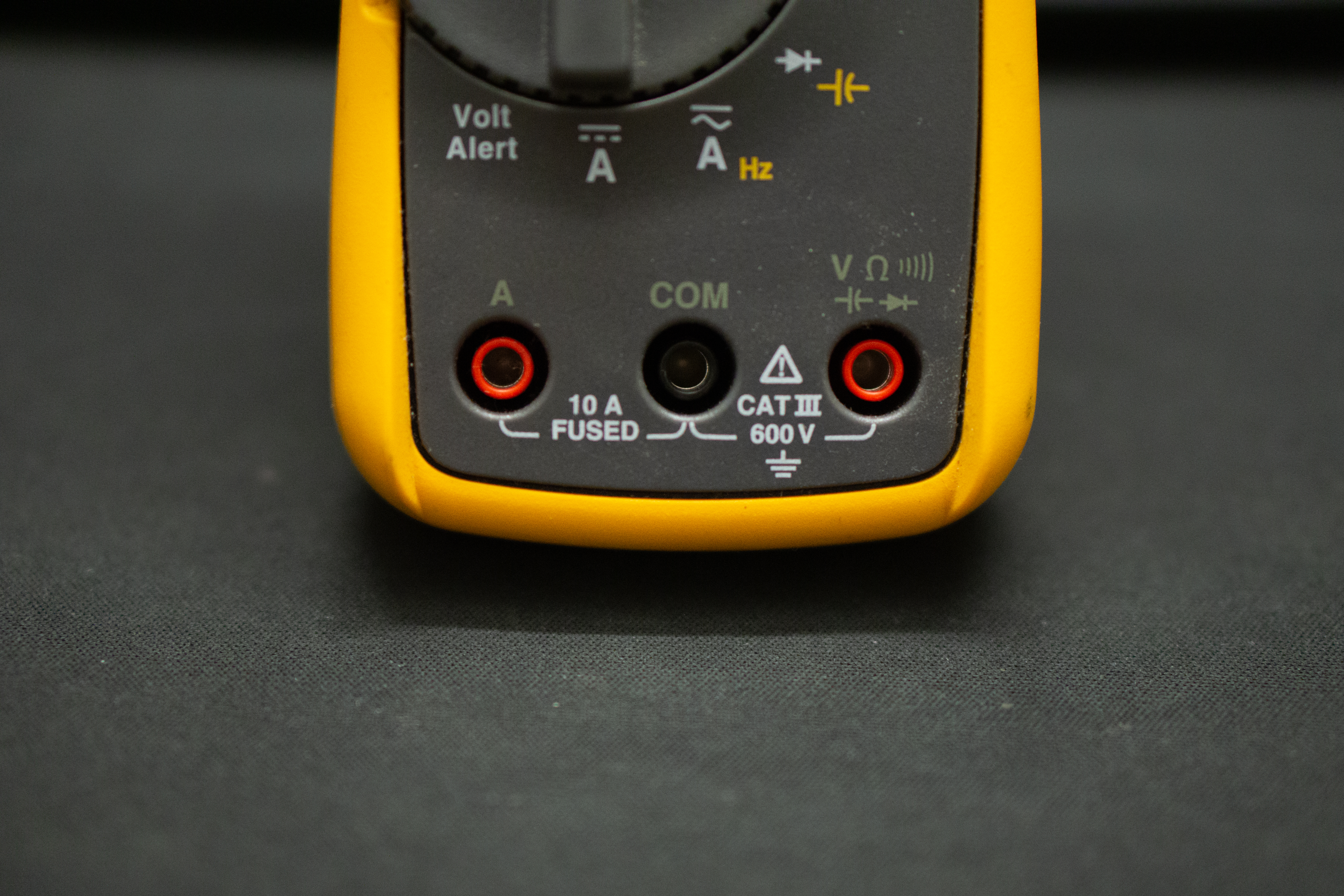
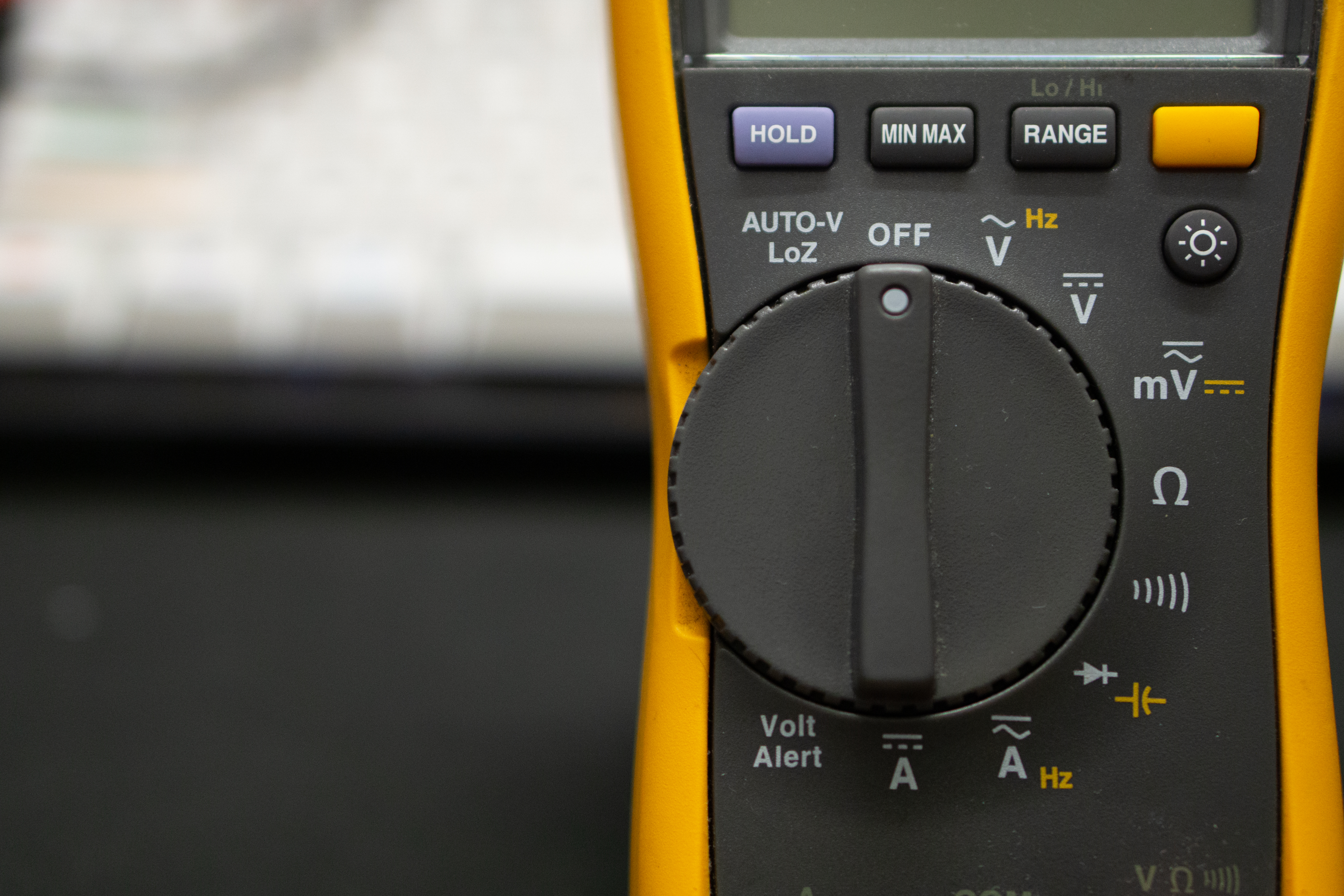
Ports
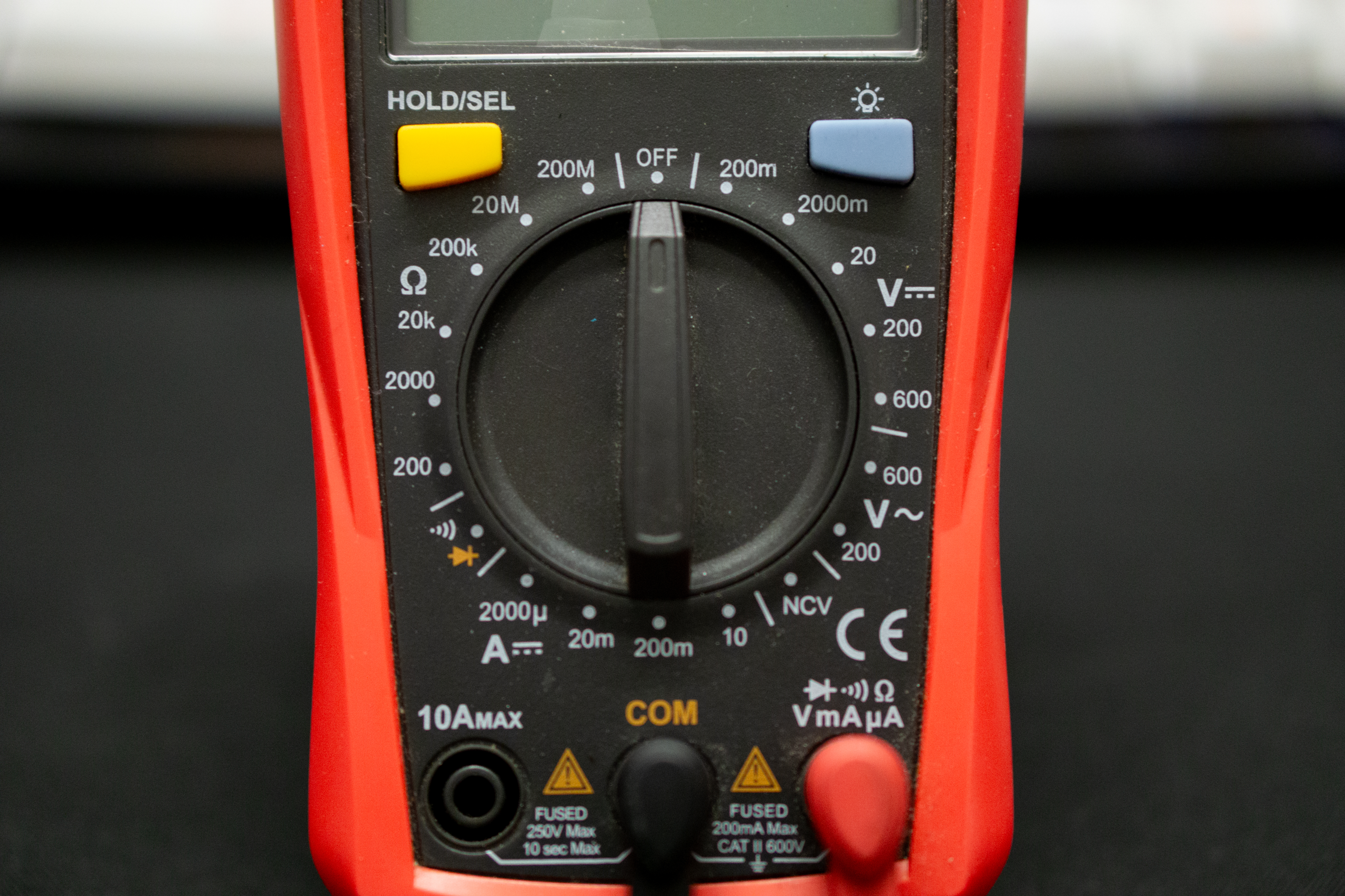
Before using a multimeter, you should take note of the ports being used on it (the red and black holes at the bottom of the device). The COM port stands for common, and is connected to ground. This is where your black probe goes. The other ports will be for the red probe, indicated by a current rating (such as 10 A) or various symbols found on the device. Ports labelled with a current rating are meant to measure large currents, while the other port is meant for low current applications (check your multimeters manual for exact specifications).
Voltage and current
The V symbol on your multimeter indicates the voltmeter setting, while the A symbol indicates the ammeter setting.
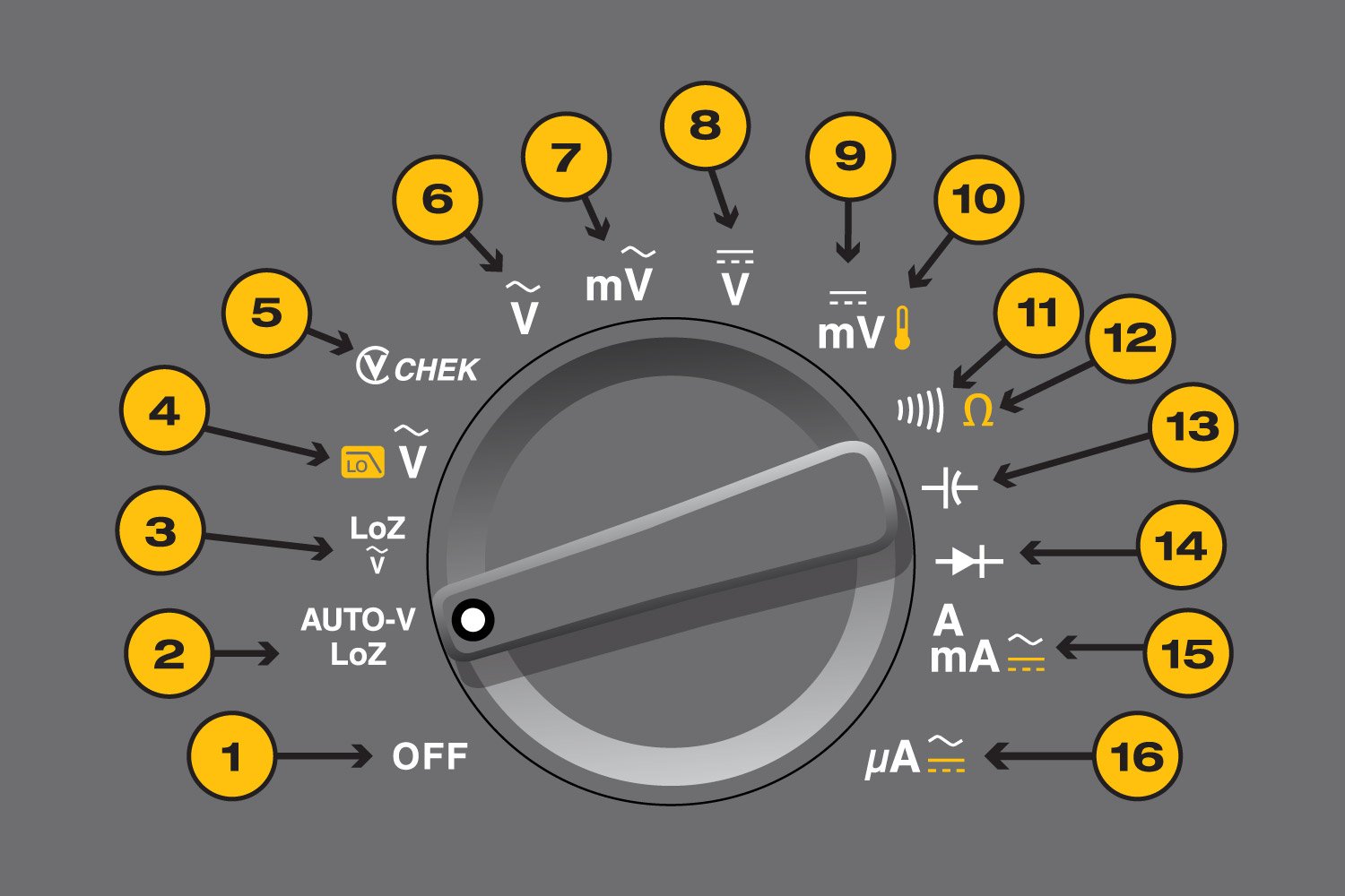
These symbol will be appended with various other symbols, such as ~, = or m (symbols 6-8). These symbols (usually) indicate AC measurement, DC measurement and voltage measurement in the millivolt range.
Instead of m, some multimeters will include the number 2 in different magnitudes, such as: 2, 20, 200, 2000. Fun fact on why the number 2 is used (hint: it's related to 7-segment displays).
The unit measured is voltage and amps respectively, with the scaling dependent on the range being measured. Alternating the orientation of the test probes would result in flipped readings, so its up to the user to be aware of the flow of current in the circuit.
Resistance
The "Ohm" symbol (symbol 12) resistance measurement and its unit of measurement is also in ohms. The orientation of the positive and negative probes of the multimeter do not affect the measured resistance.
Continuity
Continuity testing is used to check if current can flow along the tested circuit or material. A successful continuity check will result in a "beep" noise. The continuity symbol (symbol 11) looks like a 90 degree right rotated WiFi icon.
It is good practice to test the probes of the multimeter against itself to ensure that you are a) in continuity mode and b) continuity mode is functioning as intended. You should hear a beep when the probes touch each other.